CNC Pipe / Tube Bending
OTHER SERVICES
CNC Pipe / Tube Bending
Download our Brochure
Our company profile

CONTACT US TODAY

Vo Quy
Sales Manager VIETNAM
+84 982998709
Brett McMiles
Business Development / Sales Manager INTERNATIONAL
+61 428887392
Tube Bending Process
Tube bending as a process starts with loading a tube into a tube or pipe bender and clamping it into place between two dies, the clamping block and the forming die. The tube is also loosely held by two other dies, the wiper die and the pressure die.
The process of tube bending involves using mechanical force to push stock material pipe or tubing against a die, forcing the pipe or tube to conform to the shape of the die. Often, stock tubing is held firmly in place while the end is rotated and rolled around the die.
No Connections.
Consistency.
No Welding.
Cost Effective.
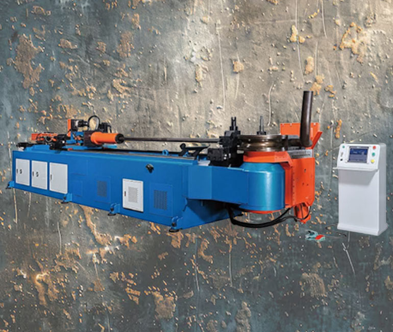
Our Machines

Horse power: 48hp
Max. Bending capacity(mm): 150×8
Max. Bending radius(mm): 500
Max. Bending angle(°): 190
Max. Feeding positioning length(mm): 4000
Max. Feeding length with mandrel(mm): 6000
Bending accuracy(°): ±0.1
Bending speed(°/sec): 5
Feeding accuracy(mm): rack ±0.1
Ballscrew –
Feeding speed(mm/sec): 1~600
Turning accuracy(°): ±0.1
Number of programs: 200
Bending no./program: 30 edit lines / program
Turning speed(°/sec): 82
Radius difference between stacks(mm): 170
Dimensions(cm): 900x250x180
Weight (kg): 18500 / 20000

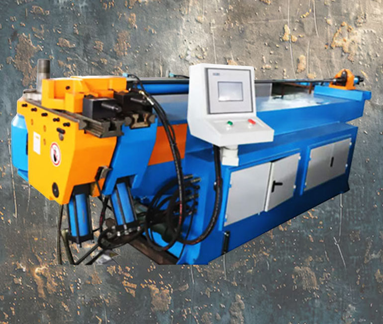
Brand: DATYSO
Model: 38CNC-2A-1S
Maximum bending capacity of carbon tube: Ø38*2mm
Maximum bending capacity of stainless steel pipe: Ø32*1.8mm
Core length: 2000mm
Tube length: 1800mm
Bending radius: R200mm
Bending angle: 185°
Bending precision: ±0.1°
Angular bending speed: 35º/s | Crankshaft rotation speed: 50º/s | Pipe Filling speed: 900mm/s
Control system: CNC Control
Hydraulic control system: Electronic valve
Oil tank: 17L/12Mpa
Material loading servo: 0.75kW
Angle bending shaft servo: 0.5kW
Crankshaft servo: 3.0kW
Material feeding accuracy: ±0.1mm
Machine size: 2600*840*1300
Machine weight: 1600kg
Frequently Asked Questions
While tube and pipe can be bent with a variety of methods, one of the most common is the rotary draw tube bending process. Done correctly, this process produces highly satisfactory results at a reasonable cost.
To follow are several commonly asked questions and the important things to know before you start bending.
What Is the Difference Between Tube and Pipe?
Often today, you may not have actual part prints available to confirm material size and dimensions. A measuring device such as vernier calipers can be used to gauge the material’s outside diameter (O.D.) and inside diameter (I.D.), which will enable you to confirm necessary dimensions and make simple drawings.
Knowing the material’s true dimensions is key to selecting the proper machine and tooling for your application. Pipe sizes are measured by I.D., with wall thickness referred to in terms of schedule. Tube sizes are based on O.D., and wall thickness is referred to in gauge sizes.
What Is the Maximum Degree of Bend?
This may sound simple; however, it is not if you are not given prints and are asked to reproduce parts from sample pieces.
Rotary draw bending tooling usually is designed to accept a maximum bend angle of 180 degrees. When selecting bending machinery for your application, be sure the machine program or system allows for slight overbending to compensate for springback during the bend cycle. Selecting a bending machine with a programmable bend angle setting can provide high bend accuracy and ease of use.
Degree of bend also affects bend quality. When working with a new material, try making two test bends—one at 45 degrees and one at 180 degrees. You may see slightly different results in the workpiece, because greater bend angles produce more wall thinning and deformation in the material.
Why Is Minimum Distance Between Bends a Factor?
Tooling for rotary bending requires a straight section of material for the forming tool to clamp the workpiece securely and prevent slippage during the bend cycle. Applications always should be reviewed for the shortest distance between any two bends, and the tooling should be manufactured to compensate for this distance if possible.
